Unit-2 Basic Computer Organization and Design
Looping
Outline
Instruction Codes
Computer Registers
Computer Instructions
Timing and Control
Instruction Cycle
Memory-Reference Instructions
Input-output and Interrupt
Complete Computer Description
Design of Accumulator Unit
Instruction Codes
- Section - 1
Instruction Codes (cont.)
- Program
- A program is a set of instructions that specify the operations, operands and the sequence by which processing has to occur.
- Computer Instruction
- A computer instruction is a binary code that specifies a sequence of micro-operations for the computer.
- The computer reads each instruction from memory and places it in a control register.
- The control then interprets the binary code of the instruction and proceeds to execute it by issuing a sequence of micro-operations.
- Instruction Code
- An instruction code is a group of bits that instruct the computer to perform a specific operation.
- Example
- Operation Code (Opcode)
- The operation code of an instruction is a group of bits that define such operations as add, subtract, multiply, shift, and complement.
- The number of bits required for the operation code of an instruction depends on the total number of operations available in the computer.
- The operation code must consist of at least n bits for a given 2n (or less) distinct operations.
- ADD 1547
- Unique Binary code is assigned to every Opcode
Stored Program Organization
Operand
(data)
Instructions
(program)
Memory
4096 x 16
Processor Register (accumulator or AC)
Opcode
Address
Instruction Format
Binary Operand
Stored Program Organization (cont.)
- The simplest way to organize a computer is to have one processor register(AC) and an instruction code format with two parts.
- The first part specifies the operation (opcode) to be performed and the second specifies an address (operand).
- The memory address tells the control where to find an operand in memory.
- This operand is read from memory and used as the data to be operated on together with the data stored in the processor register.
- Instructions are stored in one section of memory and data in another.
- For a memory unit with 4096 words, we need 12 bits to specify an address since 212 = 4096.
- If we store each instruction code in one 16-bit memory word, we have available four bits for operation code (opcode) to specify one out of 16 possible operations, and 12 bits to specify the address of an operand.
- The control reads a 16-bit instruction from the program portion of memory.
- Then it executes the operation specified by the operation code.
Addressing
- It is sometimes convenient to use the address bits of an instruction code not as an address but as the actual operand. When the second part of an instruction code specifies an operand, the instruction is said to have an immediate operand.
- When the second part specifies the address of an operand, the instruction is said to have a direct address.
- This is in contrast to a third possibility called indirect address, where the bits in the second part of the instruction designate an address of a memory word in which the address of the operand is found.
- One bit of the instruction code can be used to distinguish between a direct and an indirect address.
Direct & Indirect Addressing of Memory
- If the second part of an instruction format specifies the address of an operand, the instruction is said to have a direct address.
- In Indirect address, the bits in the second part of the instruction designate an address of a memory word in which the address of the operand is found.
ADD
457
Operand
457
Memory
AC
+
ADD
300
Operand
1350
Memory
AC
+
1350
300
Instruction format of basic computer
Instruction Format
Opcode
Address
I
| 0 | 0 | 0 | 1 | 0 | 1 | 0 | 0 | 0 | 1 | 0 | 1 | 0 | 1 | 1 | 1 |
|---|
Add Instruction – ADD 457
Direct & Indirect Addressing of Memory
A direct address instruction is placed at address 22 in memory.
- The I bit is 0, so the instruction is recognized as a direct address instruction.
- The opcode specifies an ADD instruction, and the address part is the binary equivalent of 457.
- The control finds the operand in memory at address 457 and adds it to the content of AC.
ADD
457
- The instruction in address 35 has a mode bit I = 1, recognized as an indirect address instruction.
- The address part is the binary equivalent of 300.
- The control goes to address 300 to find the address of the operand.
- The address of the operand in this case is 1350.
- The operand found in address 1350 is then added to the content of AC.
ADD
300
Computer Registers
- Section - 2
COMPUTER REGISTER
- Computer instructions are normally stored in consecutive memory locations and are executed sequentially one at a time.
- The control reads an instruction from a specific address in memory and executes it. It then continues by reading the next instruction in sequence and executes it, and so on.
- This type of instruction sequencing needs a counter to calculate the address of the next instruction after execution of the current instruction is completed.
- It is also necessary to provide a register in the control unit for storing the instruction code after it is read from memory.
- The computer needs processor registers for manipulating data and a register for holding a memory address.
- The data register (DR) holds the operand read from memory.
- The accumulator (AC) register is a general purpose processing register.
- The instruction read from memory is placed in the instruction register (IR).
- The temporary register (TR) is used for holding temporary data during the processing
Computer Registers
PC
IR
AR
- Program Counter(12)
- Holds address of instruction
- Address Register(12)
- Holds address for memory
- Instruction Register(16)
- Holds instruction code
- Temporary Register(16)
- Holds temporary data
- Data Register(16)
- Holds memory operand
TR
DR
INPR
OUTR
- Input Register(8)
- Holds input character
- Output Register(8)
- Holds output character
- Accumulator(16)
- Processor register
Memory
4096 words
16 bits per word
AC
DR AC
- OUTR
- LD
- TR
- LD
- LD
- INPR
- Memory
- 4096 x 16
- INR
- CLR
- IR
- AC
- LD
- INC
- CLR
- DR
- LD
- INC
- CLR
- PC
- LD
- INC
- CLR
- AR
- LD
- INC
- CLR
- Write
- Read
- Adder & Logic
- E
- Address
- Clock
- Bus
- S2
- S1
- S0
- Common Bus System of Basic Computer
AC DR
AC
AC
Computer Instructions
- Section - 3
COMPUTER INSTRUCTION
- The basic computer has three instruction code format. Each format has 16 bits.(Memory reference, Register Reference, input-output)
- A memory-reference instruction uses 12 bits to specify an address and one bit to specify the addressing mode I. I is equal to 0 for direct address and to 1 for indirect address.
Types of Computer Instructions
- Memory Reference Instruction
Opcode
Address
I
| 0 | 0 | 0 | 0 | Address |
|---|
0xxx
AND
AND the content of memory to AC
8xxx
1xxx
ADD
Add the content of memory to AC
9xxx
2xxx
LDA
Load memory word to AC
Axxx
3xxx
STA
Store content of AC in memory
Bxxx
4xxx
BUN
Branch unconditionally
Cxxx
5xxx
BSA
Branch and save return address
Dxxx
6xxx
ISZ
Increment and skip if zero
Exxx
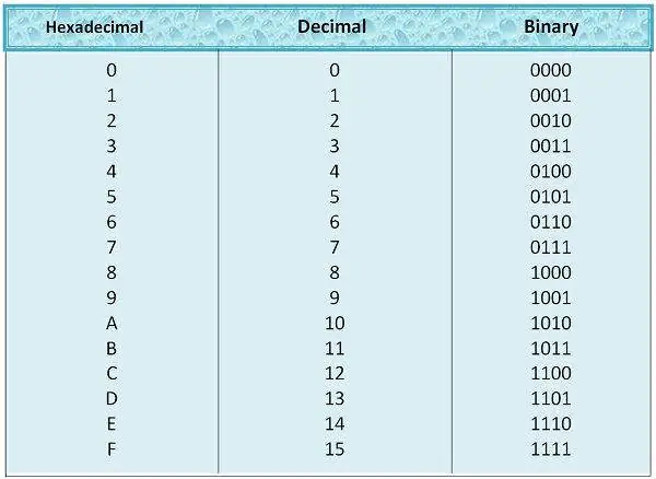
(for instructions hexadecimal is used)
| 0 | 0 | 0 | 0 | Address Bits |
|---|---|---|---|---|
| 0XXX – AND |
| 0 | 0 | 0 | 1 | Address Bits |
|---|---|---|---|---|
| 1XXX - ADD |
| 0 | 0 | 1 | 0 | Address Bits |
|---|---|---|---|---|
| 2XXX-LDA |
Slide 19
Register Reference Instruction
- The register reference instructions are recognized by the operation code Ill with a 0 in the leftmost bit (bit 15) of the instruction.
- A register-reference instruction specifies an operation on or a test of the AC register.
- An operand from memory is not needed; therefore, the other 12 bits are used to specify the operation or test to be executed.
- Note that the bit in position 15 of the instruction code is designated by the symbol I but is not used as a mode bit when the operation code is equal to 1 1 1 .
REGISTER REFERENCE
| 0 | 1 | 1 | 1 | 1 | 0 | 0 | 0 | 0 | 0 | 0 | 0 | 0 | 0 | 0 | 0 |
|---|---|---|---|---|---|---|---|---|---|---|---|---|---|---|---|
| 7800 – CLA |
| 0 | 1 | 1 | 1 | 0 | 1 | 0 | 0 | 0 | 0 | 0 | 0 |
|---|---|---|---|---|---|---|---|---|---|---|---|
| 7400 - CLE |
| 0 | 1 | 1 | 1 | 0 | 0 | 1 | 0 | 0 | 0 | 0 | 0 |
|---|---|---|---|---|---|---|---|---|---|---|---|
| 7200-CMA |
Types of Computer Instructions
- Register Reference Instruction
7800
CLA
Clear AC
7400
CLE
Clear E
7200
CMA
Complement AC
7100
CME
Complement E
7080
CIR
Circulate right AC and E
7040
CIL
Circulate left AC and E
7020
INC
Increment AC
| 0 | 1 | 1 | 1 | 0 | 0 | 0 | 0 | 0 | 0 | 0 | 0 | 0 | 0 | 0 | 0 |
|---|
Register Operation
Types of Computer Instructions (cont.)
- Register Reference Instruction
7010
SPA
Skip next instruction if AC is positive
7008
SNA
Skip next instruction if AC is negative
7004
SZA
Skip next instruction if AC is zero
7002
SZE
Skip next instruction if E is zero
7001
HLT
Halt computer
| 0 | 1 | 1 | 1 | 0 | 0 | 0 | 0 | 0 | 0 | 0 | 0 | 0 | 0 | 0 | 0 |
|---|
Register Operation
Input Output Instruction
- an input-output instruction does not need a reference to memory and is recognized by the operation code with a 1 in the leftmost bit of the instruction and 111 in remaining three opcode bits.
- The remaining 12 bits are used to specify the type of input-output operation or test performed.
Types of Computer Instructions
- Input – Output Instruction
F800
INP
Input character to AC
F400
OUT
Output character from AC
F200
SKI
Skip on input flag
F100
SKO
Skip on output flag
F080
ION
Interrupt on
| 1 | 1 | 1 | 1 | 0 | 0 | 0 | 0 | 0 | 0 | 0 | 0 | 0 | 0 | 0 | 0 |
|---|
I/O Operation
F040
IOF
Interrupt off
Instruction Set Completeness
- Instruction set is said to be complete if it includes enough instructions in each of the following
Arithmetic, logic, and shift instructions
- ADD, CMA, INC, CIR, CIL, AND, CLA
- Transfer Instructions :Data transfers between the main memory and the processor registers
- LDA, STA
Control Instructions : Program sequencing and control
- BUN, BSA, ISZ
Input/Output Instructions :Input and output
- INP, OUT
Timing and Control
- Section - 4
Control Organization
- Hardwired Control
- The control logic is implemented with gates, flips-flops, decoders and other digital circuits.
It can be optimized to produce a fast mode of operation.
- It requires changes in the wiring among the various components if the design has to be modified or changed.
- Microprogrammed Control
The control information is stored in a control memory.
- The control memory is programmed to initiate the required sequence of micro-operations.
- Any required changes or modifications can be done by updating the microprogram in control memory.
Control Unit
- Components of Control unit are
- Two decoders
- A sequence counter
- Control logic gates
- An instruction read from memory is placed in the instruction register (IR).
- In control unit the IR is divided into three parts: I bit, the operation code (12-14)bit, and bits 0 through 11.
- The operation code in bits 12 through 14 are decoded with a 3 x 8 decoder.
- Bit-15 of the instruction is transferred to a flip-flop designated by the symbol I.
- The eight outputs of the decoder are designated by the symbols D0 through D7.
- Bits 0 through 11 are applied to the control logic gates.
- The 4‐bit sequence counter can count in binary from 0 through 15. The outputs of counter are decoded into 16 timing signals T0 through T15.
- The sequence counter SC can be incremented or cleared synchronously.
Control Unit of Basic Computer
| 15 | 14 | 13 | 12 | 11 - 0 |
|---|
Instruction Register
Control Logic Gates
- 3 x 8
- Decoder
- 7 6 5 4 3 2 1 0
- 4 x 16
- Decoder
- 15 14 . . . 2 1 0
I
- 4-bit sequence counter (SC)
Other inputs
- Control O/p
D0
D7
T15
T0
- Increment (INC)
- Clear (CLR)
- Clock
| 0 | 0 | 0 | 1 | 0 | 1 | 0 | 0 | 0 | 1 | 0 | 1 | 0 | 1 | 1 | 1 |
|---|
D1
Control Unit
- Most of the time, the counter is incremented to provide the sequence of timing signals out of 4 X 16 decoder.
- Once in awhile, the counter is cleared to 0, causing the next timing signal to be T0.
- As an example, consider the case where SC is incremented to provide timing signals T0, T1, T2, T3 and T4 in sequence. At time T4, SC is cleared to 0 if decoder output D3 is active. This is expressed symbolically by the statement
- D3T4: SC ← 0
- Initially, the CLR input of SC is active.
- The first positive transition of the clock clears SC to 0, which in turn activates the timing T0 out of the decoder.
- T0 is active during one clock cycle.
- The positive clock transition labeled T0 in the diagram will trigger only those registers whose control inputs are connected to timing signal T0.
Control Unit (cont.)
- SC is incremented with every positive clock transition, unless its CLR input is active.
- This procedures the sequence of timing signals T0, T1, T2, T3 and T4, and so on. If SC is not cleared, the timing signals will continue with T5, T6, up to T15 and back to T0.
- The last three waveforms shows how SC is cleared when D3T4 = 1.
- Output D3 from the operation decoder becomes active at the end of timing signal T2.
- When timing signal T4 becomes active, the output of the AND gate that implements the control function D3T4 becomes active.
- This signal is applied to the CLR input of SC.
- On the next positive clock transition the counter is cleared to 0.
- This causes the timing signal T0 to become active instead of T5 that would have been active if SC were incremented instead of cleared.
Timing Cycle for D3T4: SC ← 0
- Clock
- CLR SC
Instruction Cycle
- Section - 5
Instruction Cycle (cont.)
- A program residing in the memory unit of the computer consists of a sequence of instructions. In the basic computer each instruction cycle consists of the following phases:
- Fetch an instruction from memory.
- Decode the instruction.
- Read the effective address from memory if the instruction has an indirect address.
- Execute the instruction.
- After step 4, the control goes back to step 1 to fetch, decode and execute the next instruction.
- This process continues unless a HALT instruction is encountered.
Slide 37
- Start
- SC ← 0
- AR ← PC
- IR ← M[AR], PC ← PC + 1
- Decode operation code in IR(12-14)
- AR ← IR(0-11), I ← IR(15)
- D7
- I
- I
- Execute input-output instruction
- SC ← 0
- Execute
- register-reference instruction
- SC ← 0
- AR ← M[AR]
- Nothing
- Execute
- memory-reference instruction
- SC ← 0
- (Register or I/O) = 1
- = 0 (Memory-reference)
- (I/O) = 1
- = 0 (register)
- (indirect) = 1
- = 0 (direct)
Input-output and Interrupt
- Section - 7
Input-Output of basic computer
- A computer can serve no useful purpose unless it communicates with the external environment.
- To exhibit the most basic requirements for input and output communication, we will use a terminal unit with a keyboard and printer.
- The terminal sends and receives serial information and each quantity of information has eight bits of an alphanumeric code.
- The serial information from the keyboard is shifted into the input register INPR.
- The serial information for the printer is stored in the output register OUTR.
- These two registers communicate with a communication interface serially and with the AC in parallel.
- The input register INPR consists of eight bits and holds an alphanumeric input information. The 1-bit input flag FGI is a control flip-flop.
- The flag bit is set to 1 when new information is available in the input device and is cleared to 0 when the information is accepted by the computer.
Input-Output of basic computer (cont.)
- Keyboard
- Transmitter Interface
- INPR
- AC
- OUTR
- FGO
- FGI
- Printer
- Receiver Interface
- Input-Output terminal
- Serial communication interface
- Computer registers and flip-flop
- =0
- =1
- =1
- =0
Process of input & output information transfer
- Initially, the input flag FGI is cleared to 0. When a key is struck in the keyboard, an 8-bit alphanumeric code is shifted into INPR and the input flag FGI is set to 1.
- As long as the flag is set, the information in INPR cannot be changed by striking another key. The computer checks the flag bit; if it is 1, the information from INPR is transferred in parallel into AC and FGI is cleared to 0.
- Once the flag is cleared, new information can be shifted into INPR by striking another key.
- The output register OUTR works similarly but the direction of information flow is reversed.
Initially, the output flag FGO is set to 1. The computer checks the flag bit; if it is 1, the information from AC is transferred in parallel to OUTR and FGO is cleared to 0. The output device accepts the coded information, prints the corresponding character, and when the operation is completed, it sets FGO to 1.
The computer does not load a new character into OUTR when FGO is 0 because this condition indicates that the output device is in the process of printing the character.
Input Transfer
Output Transfer
Input-Output Instruction
D7IT3 = p (common to all input-output instructions)
IR(i) = Bi [bit in IR(6-11) that specifies the operation]
INP
pB11
AC(0-7) ← INPR, FGI ← 0
Input Character
OUT
pB10
OUTR ← AC(0-7), FGO ← 0
Output Character
SKI
pB9
If (FGI = 1) then (PC ← PC + 1)
Skip on input flag
SKO
pB8
If (FGO = 1) then (PC ← PC + 1)
Skip on output flag
ION
pB7
IEN ← 1
Interrupt enable on
IOF
pB6
IEN ← 0
Interrupt enable off
Interrupt Cycle
- R
- Fetch & Decode instruction
- Store return address in location 0
- M[0] ← PC
- Execute instruction
- IEN
- FGI
- FGO
- R ← 1
- Branch to location 1
- PC ← 1
- IEN ← 0
- R ← 0
- = 0
- = 1
- Interrupt cycle
- Instruction cycle
- = 1
- = 0
- = 1
- = 0
- = 1
- = 0
Interrupt Cycle (cont.)
- The interrupt cycle is a hardware implementation of a branch and save return address operation.
- An interrupt flip-flop R is included in the computer.
- When R = 0, the computer goes through an instruction cycle.
- During the execute phase of the instruction cycle IEN is checked by the control.
- If it is 0, it indicates that the programmer does not want to use the interrupt, so control continues with the next instruction cycle.
- If IEN is 1, control checks the flag bits.
- If both flags are 0, it indicates that neither the input nor the output registers are ready for transfer of information.
- In this case, control continues with the next instruction cycle. If either flag is set to 1 while IEN = 1, flip-flop R is set to 1.
- At the end of the execute phase, control checks the value of R, and if it is equal to 1, it goes to an interrupt cycle instead of an instruction cycle.
Register transfer statements for Interrupt cycle
- The flip-flop is set to 1 if IEN = 1 and either FGI or FGO are equal to 1. This can happen with any clock transition except when timing signals T0, T1 or T2 are active.
- The condition for setting flip-flop R = 1 can be expressed with the following register transfer statement:
- T0 T1 T2 (IEN) (FGI + FGO): R 1
- The symbol + between FGI and FGO in the control function designates a logic OR operation. This is AND with IEN and T0 T1 T2.
- The fetch and decode phases of the instruction cycle must be modified and Replace T0, T1, T2 with R'T0, R'T1, R'T2
- Therefore the interrupt cycle statements are :
- RT0 : AR 0, TR PC
- RT1 : M[AR] TR, PC 0
- RT2 : PC PC + 1, IEN 0, R 0, SC 0
Register transfer statements for Interrupt cycle (cont.)
- During the first timing signal AR is cleared to 0, and the content of PC is transferred to the temporary register TR.
- With the second timing signal, the return address is stored in memory at location 0 and PC is cleared to 0.
- The third timing signal increments PC to 1, clears IEN and R, and control goes back to T0 by clearing SC to 0.
- The beginning of the next instruction cycle has the condition RT0 and the content of PC is equal to 1. The control then goes through an instruction cycle that fetches and executes the BUN instruction in location 1.
Design of Accumulator Unit
- Section - 9
Design of Accumulator Logic
- In order to design the logic associated with AC, it is necessary to extract all the statements that change the content of AC.
D0T5: AC AC DR, SC 0
AND with DR
D1T5: AC AC + DR, SC 0
ADD with DR
D2T5: AC DR
Transfer from DR
pB11: AC(0-7) ← INPR, FGI ← 0
Transfer from INPR
rB9: AC ← AC’
Complement
rB7: AC ← shr AC, AC(15) ← E
Shift right
rB6: AC ← shl AC, AC(0) ← E
Shift left
rB11: AC ← 0
Clear
rB5: AC ← AC + 1
Increment
Design of Accumulator Logic (cont.)
Circuit associated with AC
- Adder and logic circuit
- Accumulator register (AC)
- Control gates
- CLR
- INR
- LD
- Clock
- From DR
- From INPR
- To bus
Design of Accumulator Logic (cont.)
Gate structure for controlling LD, INR and CLR of AC
- AC
- CLR
- INR
- LD
- Clock
- To bus
- AND
- ADD
- DR
- INPR
- CMA
- SHR
- SHL
- INC
- CLR
- D0
- T5
- D1
- D2
- T5
- p
- B11
- r
- B9
- B7
- B6
- B5
- B11
- From Adder & Logic